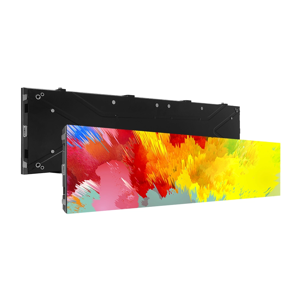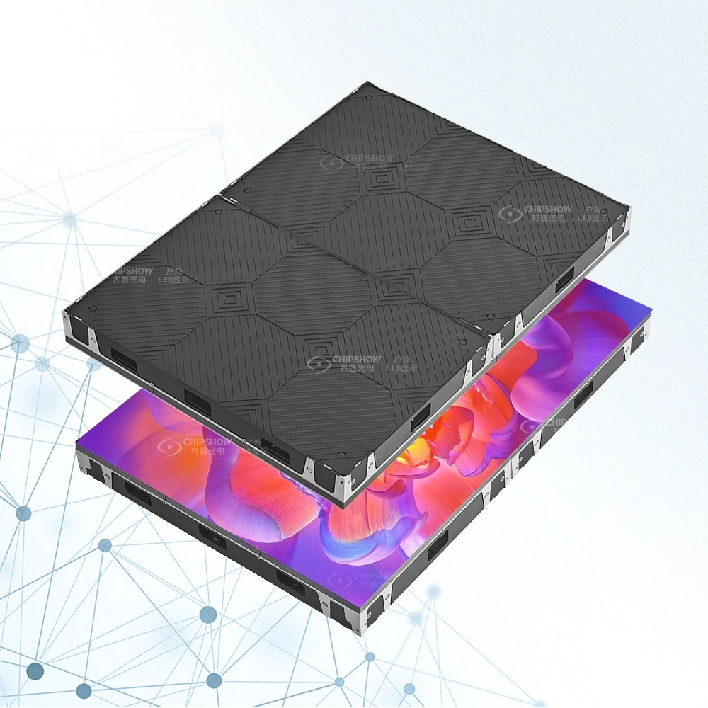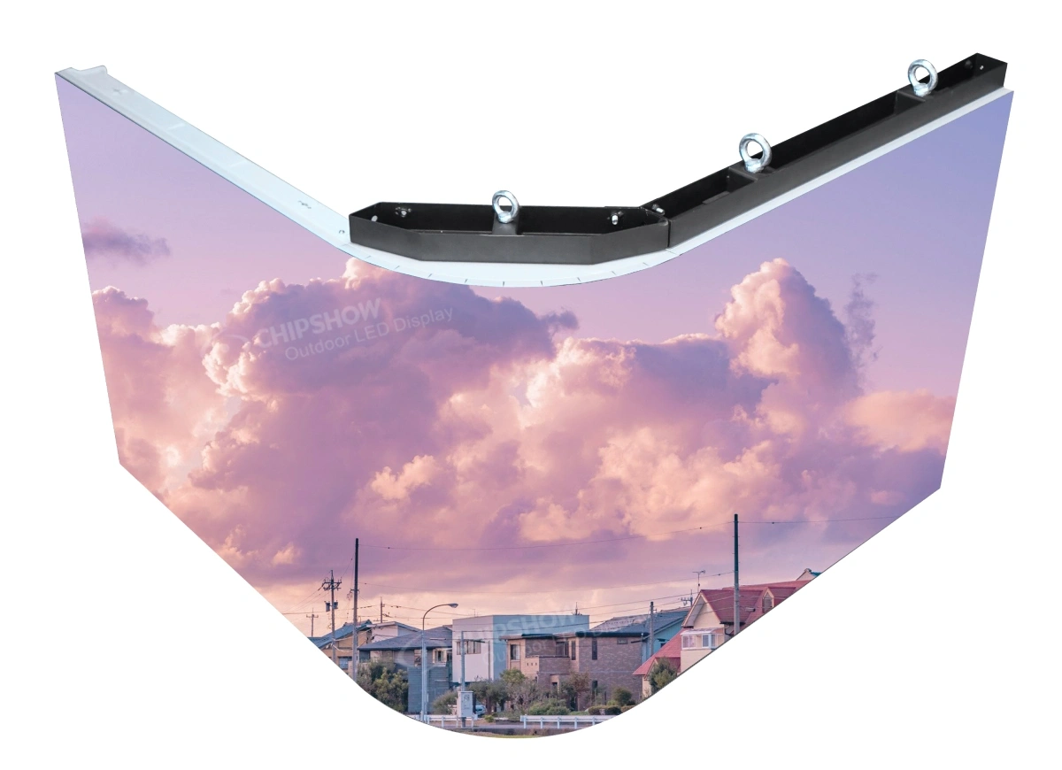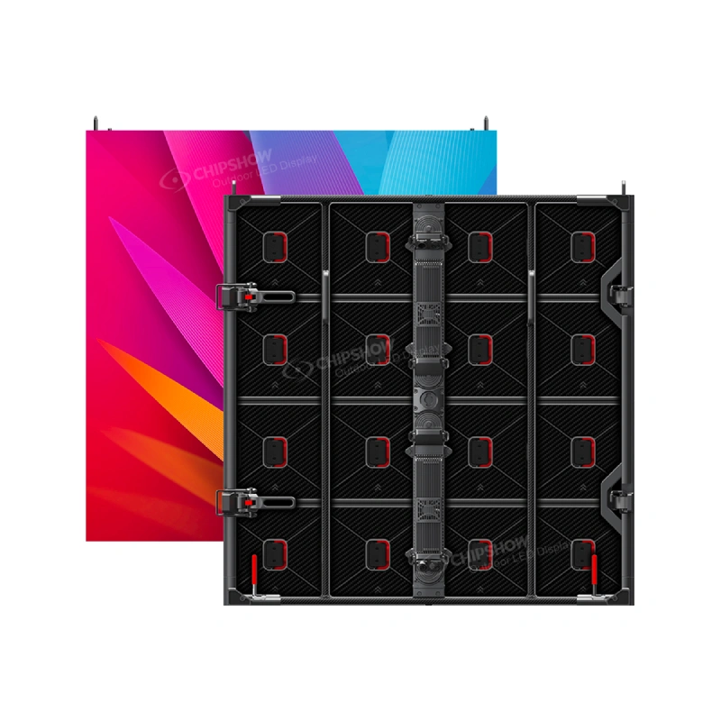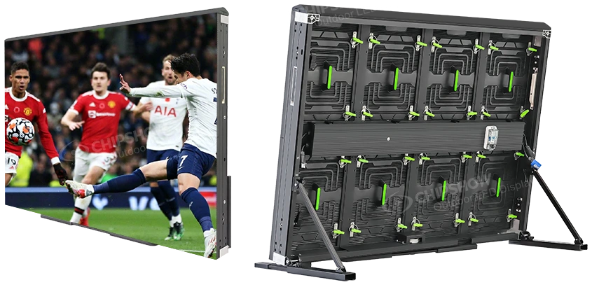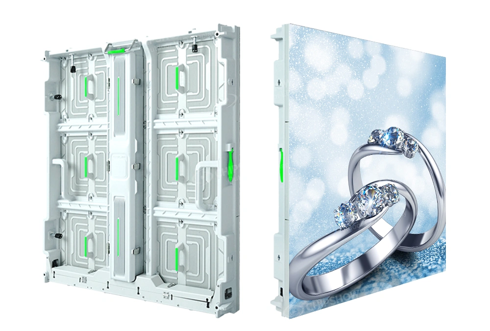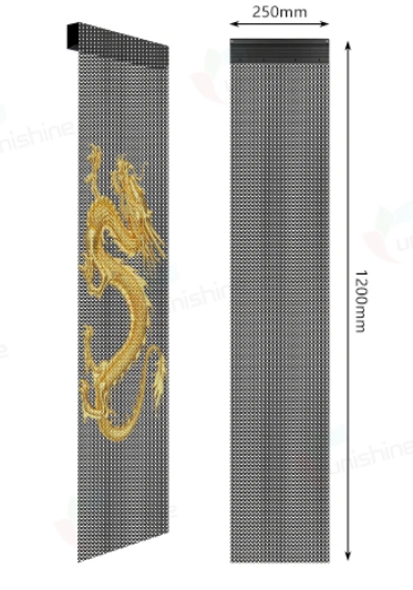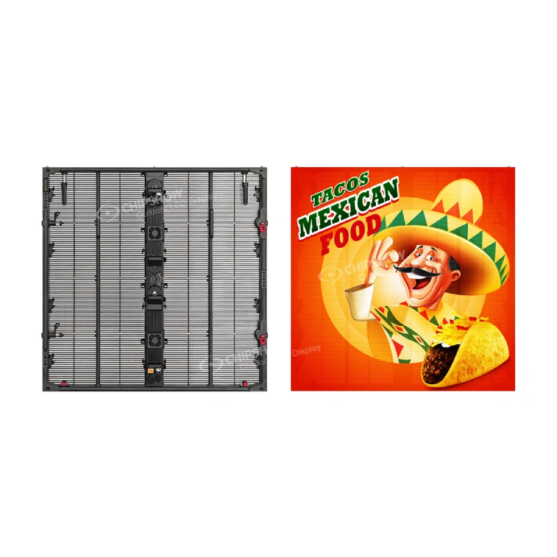
A pre-installation verification checklist for sign fabricators, electrical contractors and control-system integrators. Frame, wiring and control are settled before metal is cut. A sign fabricator avoids rework by confirming the key inputs up front: module dimensions and tolerance, power distribution and grounding, receiving card and data routing, and local code compliance. National Electrical Code (NEC) Article 600 sets the North American baseline for outdoor sign wiring. Work the checklist in that order, and each check maps to a 320×320 mm module on the C-Fit-Easy platform.
No se monta un cartel a partir de una hoja técnica: un módulo que encaja en papel sigue fallando en el taller si la abertura del armario se cortó a un tamaño nominal, se adivinó el número de fuentes de alimentación o se seleccionó la tarjeta receptora sin un plan de enrutamiento de datos. Registra cada artículo confirmado con el nombre de la persona que lo revisó y la fecha, para que la tienda lleve un registro escrito de lo que se verificó y cuándo para la inspección.
Cinco entradas para verificar antes de empezar
Un fabricador de carteles que empieza a cortar metal antes de que estas entradas estén bloqueadas está cortando dos veces. Confirma las cinco entradas en relación con los planos del proveedor y los planos eléctricos y estructurales del proyecto:
- Configuración del módulo congelada. Registra el dibujo específico del módulo, no el apellido ni el tamaño nominal. Las dimensiones nominales no capturan tolerancias, proyecciones de conectores, espacio de flexión del cable ni acceso de los sujetadores.
- Área de visualización activa y matriz de píxeles bloqueados. La disposición citada debe coincidir con la elevación del signo, incluyendo cuántos módulos circulan en cada fila y columna. Pide al proveedor que devuelva la matriz de píxeles resultante para el array específico citado, para que el equipo de contenido pueda renderizar el mensaje real antes de que se corte la cara.
- Dirección de servicio decidida. El servicio delantero y trasero cambia la profundidad del armario, los rieles interiores y el separador de la pared. Decide antes del diseño de la carcasa, porque un módulo de servicio trasero montado en un armario construido para el servicio frontal se convierte en un problema de reemplazo.
- Base eléctrica registrada. Anote el voltaje disponible, la ubicación del alimentador, la posición de desconexión y el horario de funcionamiento. La cantidad de la fuente de alimentación y el diseño del circuito ramal derivan de estas entradas, no de una regla general.
- Camino de control nombrado. Identifica la tarjeta receptora, el emisor, el software y la ruta de red. El hardware de control se elige en función de la interfaz de datos del módulo y el flujo de trabajo de contenido, no se añade al final.
Tolerancia del chasis, montaje y ventilación
Una abertura de recinto cortada a una dimensión redondeada puede dejar módulos que se atajan en las esquinas o huecos por donde entran el agua y los insectos. Haz estas cuatro comprobaciones antes de que el metal se libere:
- Presupuesto de tolerancia verificado en todo el conjunto. Un módulo puede mantener una tolerancia por sí solo, pero una fila de diez módulos acumula error. El dibujo del gabinete debe distinguir la abertura visible de la apertura física y mostrar cómo se acumulan las tolerancias del primer módulo al último.
- Interfaz de montaje confirmada. Comprueba el patrón de agujeros, los puntos de acoplamiento, el tipo de sujetador y el camino de retirada para cada posición del módulo. Un módulo que encaje limpiamente en el centro de la matriz aún puede enlazarse contra un riel de borde o una pieza de recorte en una esquina.
- Ventilación y camino de drenaje verificados. Los carteles exteriores se calientan bajo el sol directo, y el calor atrapado acorta la vida útil de los componentes. Confirma el camino de aire a través del armario, las aberturas de drenaje y cómo se aleja el agua de la electrónica. La ventilación y el sellado se diseñan conjuntamente; Un armario que sella bien pero no puede respirar condensará la humedad internamente.
- Traspaso estructural definido. La carga muerta, la carga del viento, la estructura de soporte y la cimentación corresponden al profesional estructural responsable. El proveedor del módulo proporciona el peso del módulo y los requisitos de montaje; El ingeniero estructural evalúa el cartel y el terreno completos. No se puede asumir una clasificación de viento a partir de una hoja técnica de módulo.
Las revisiones de bastidores terminan con una pregunta: ¿puede un técnico quitar y reemplazar un módulo en el borde, la esquina y detrás del moldura con las herramientas que realmente estarán en el lugar?
Distribución de Energía, Puesta a Tierra y Cumplimiento de Normativas
El cableado es cuando un cartel pasa la inspección o detiene el proyecto. La línea base norteamericana es el Código Eléctrico Nacional (NEC), y el Artículo 600 regula las señales eléctricas y la iluminación de contorno. Un fabricador que trabaja en Estados Unidos considera el Artículo 600 del NEC como mínimo, siendo la autoridad local quien tiene jurisdicción (AHJ) como última palabra. Confirma los seis puntos que aparecen a continuación:
- Desconectarse significa localizado. El artículo 600 del NEC exige un medio de desconexión para el cartel, situado donde pueda alcanzarse para el servicio y donde el Tribunal de Justicia lo requiera. Confirma la ubicación del desconector y su calificación con el electricista antes de que se retire el alimentador.
- La distribución de potencia está diseñada a partir de la carga, no del conteo. Suma la potencia del módulo por sección de armario y luego dimensiona cada fuente de alimentación respecto a su carga real y el margen de altura. Confirma el número de módulos que sirve cada suministro y los requisitos resultantes del interruptor. El diseño del circuito ramificado, el dimensionamiento de conductores y la protección contra sobrecorriente son realizados por el diseñador eléctrico autorizado del lugar.
- Método de cableado y enrutamiento confirmados. Los carteles exteriores suelen estar cableados con conductos o con un método reconocido de cable exterior, con entradas de cable, alivio de tensión y separación entre los tramos de alimentación y datos que se muestran en el dibujo. El enrutamiento conductor debe mantener la energía alejada de la ruta de datos para evitar interferencias, y cada entrada debe estar sellada contra el agua.
- Arraigo y vínculo definidos. La puesta a tierra y la fianza cumplen con el Artículo 250 del NEC y los requisitos de la Justicia Suprema de la Justicia. Confirma el camino de unión desde el armario hasta los marcos del módulo y el método de puesta a tierra en el signo. Los objetivos específicos de resistencia a tierra varían según la jurisdicción, por lo que el contratista eléctrico confirma el número para el lugar en lugar de aplicar una cifra universal.
- Circuitos de ubicación húmeda protegidos. Los circuitos en lugares húmedos y los enchufes de conveniencia en el cartel están protegidos según lo requiera el NEC, incluyendo la protección contra fallos a tierra donde la AHJ la aplica. Confirma el tipo de protección y la clasificación con la ubicación final de cada circuito.
- Componentes listados verificados. Se espera que los signos y componentes de señalización estén listados según la norma aplicable, como UL 48 para señales eléctricas o UL 879 para componentes de señalización. Un certificado de componente no aprueba la firma completa; el AHJ revisa la instalación ensamblada. Las certificaciones no garantizan la aprobación local. Se puede proporcionar documentación del producto. Las aprobaciones finales deben confirmarse por proyecto.
| Referencia del NEC | Qué confirmar en el proyecto |
| Artículo 600 | Medios de desconexión, componentes listados, método de cableado y protección contra la ubicación húmeda |
| Artículo 250 | Camino de conexión a tierra y unión desde el armario hasta los marcos de módulos y hasta la tierra |
La sección de cableado está completa cuando el diagrama unifilar, el camino de puesta a tierra y el esquema de protección coinciden con el armario tal como se construyó.
Tarjetas receptoras y enrutamiento de datos
Control es la capa que convierte un panel iluminado en un cartel. La tarjeta receptora se empareja con la interfaz de datos del módulo, y el plan de enrutamiento decide si la señal sigue funcionando cuando falla un segmento. Confirma los cuatro puntos que se muestran a continuación:
- Confirmación de la coincidencia de tarjeta de recepción y módulo. Cada familia de módulos trabaja con tarjetas receptoras específicas, y la carga de la tarjeta determina cuántos módulos puede manejar. Confirma el modelo de la tarjeta con la interfaz del módulo y la guía de carga del proveedor antes de hacer el pedido, en lugar de seleccionar una tarjeta por costumbre.
- Enrutamiento de datos planificado. Mapea la ruta de señal desde el emisor o controlador a través de cada tarjeta receptora hasta los módulos a los que sirve. Un signo simple puede ejecutar una cadena sencilla, mientras que un signo más grande puede necesitar una topología que evite que un fallo de una sola carta destruya toda la cara. Confirma el método de redundancia con el proveedor de control para la disposición real del armario.
- Configuración registrada. Guarda el archivo de mapeo, las versiones de firmware y software, la configuración de red y el flujo de trabajo de contenido. Una configuración que solo existe en el portátil del técnico es una configuración perdida. Guarda la copia de seguridad con los registros del proyecto para que el signo pueda restaurarse desde una configuración guardada.
- Prueba de traspaso confirmada. Antes de que el cartel salga del taller, ejecuta la revisión del laboratorio: mapeo, contenido representativo, reinicio y comportamiento de comunicación, y recuperación desde la configuración guardada. La prueba debe identificar la configuración probada, la fecha, el revisor y la disposición de cualquier elemento abierto.
Control termina con un diagrama señal-flujo que muestra cada tarjeta, el módulo que alimenta y cómo se recupera el signo.
Aplicación de la lista de verificación a módulos 320×320
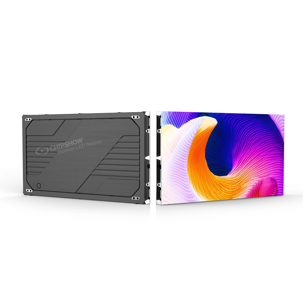
Las comprobaciones anteriores se concretan en un módulo de 320×320 mm. Este formato es un bloque común de construcción para señales exteriores, y las mismas cuestiones de marco, cableado y control se aplican de forma fija. La tabla mapea cada área de control al formato 320×320 mm y a la plataforma C-Fit-Easy:
| Revisar área | Qué confirmar en un módulo de 320×320 mm | Plataforma C-Fit-Easy |
| Marco | Presupuesto de tolerancia bloqueado antes de cortar, ya que un array se construye por multiplicación | Gabinete de fundición a presión; La documentación del producto indica una tolerancia de armario inferior a 0,1 mm para el armario de fundición a presión C-Fit-Easy descrito |
| Rango de módulos | Confirma la mecánica del módulo, la compatibilidad de energía y térmica antes de cualquier sustitución | Gabinete descrito como compatible con módulos desde P4 hasta P20, lo que proporciona al fabricante un rango para diseñar |
| Cableado | Confirma la clasificación de Protección contra Entrada (IP) del módulo según IEC 60529 | La clasificación de protección del módulo establece la expectativa de sellado |
| Control | Confirma el modelo de la tarjeta receptora y la topología de enrutamiento con el conteo real de módulos, y almacena el archivo de mapeo con los registros del proyecto | Tarjeta receptora elegida en función de la interfaz de datos del módulo y del límite de carga de la tarjeta |
Dos advertencias en la tabla de arriba. Primero, una tolerancia establecida solo es útil cuando se conoce su base de medición, así que confirma la definición y el método de inspección antes de tratarlo como una entrada de ingeniería. En segundo lugar, la clasificación IP del módulo se especifica bajo la IEC 60529 y define su resistencia al polvo y al agua; Confirma la valoración real y el sellado de entrada frente a la exposición del sitio en lugar de asumir un valor.
Para un cartel monumental, un centro de mensajes electrónicos (EMC) o un pilón junto a la carretera, el módulo de 320×320 mm reduce las preguntas de bastidor, cableado y control a un conjunto repetible.
Conclusión
El marco, el cableado y el control se leen como tres tareas separadas, pero son un solo plan. Bloquear primero el plano del módulo y la base eléctrica, llevar el presupuesto de tolerancias a lo largo de toda la matriz, aplicar el Artículo 600 del NEC y las comprobaciones de puesta a tierra al armario terminado, y registrar la configuración de control con el proyecto. Seguir la lista de comprobación en ese orden detecta los errores caros antes de que se corte el metal. Comparte el plano de señalización, la base eléctrica del sitio y los requisitos de control con Chipshow para revisar el módulo adecuado de 320×320 mm y su documentación de integración. Contácto para soporte específico de configuración y cableado de proyectos.
Preguntas frecuentes
P1: ¿Cómo cableo un módulo LED exterior 320×320?
Dimensiona la fuente de alimentación frente a la carga real del módulo y la margen de altura, dirige la energía fuera del camino de datos, sella cada entrada de cable contra el agua y confirma que la clasificación IP del módulo según IEC 60529 coincide con la exposición en el sitio. Aplica las comprobaciones del Artículo 600 del NEC para desconexión, puesta a tierra y protección al armario terminado.
P2: ¿Quién es el propietario del diseño eléctrico, del taller de señalización o del contratista eléctrico autorizado?
El diseño del circuito ramificado, el dimensionamiento de los conductores, la protección contra sobrecorriente y la confirmación de resistencia a tierra corresponden al diseñador eléctrico autorizado del lugar, ya que ellos tienen la responsabilidad de cumplir. El taller de señalización suministra las entradas de las que depende el diseño eléctrico: la carga del módulo por sección de armario, la dirección de servicio, la posición de desconexión y el horario de operación.
P3: ¿Qué documentos deben estar listos para el AHJ en la inspección?
El diagrama de una sola línea, el camino de conexión a tierra y unión, los certificados de los componentes listados, el registro de configuración de control y una nota escrita de los documentos que el AHJ ha solicitado revisar. Tener el dibujo de fotogramas, el diagrama de una sola línea y el diagrama señal-flujo fechados en la misma revisión del gabinete mantiene la presentación consistente.
P4: ¿Qué debe registrarse cuando un módulo se reemplaza en el campo?
Registra el dibujo y la revisión del módulo de reemplazo, la fecha, la persona que realiza el trabajo y la confirmación de que el módulo cumple con los requisitos mecánicos, eléctricos y térmicos del conjunto. Una nota de reemplazo vinculada a la revisión del armario mantiene el registro tal y como se construyó con precisión para la siguiente inspección.
P5: ¿Puede un módulo de servicio frontal reemplazar a un módulo de servicio trasero en el mismo armario?
El servicio delantero y trasero son diseños de armario diferentes. Cambian la profundidad del armario, los rieles internos y el separador de la pared, por lo que un módulo de servicio trasero montado en un armario construido para el servicio frontal se convierte en un problema de reemplazo. La dirección del servicio se decide antes del diseño del recinto, antes de que sea necesario reemplazarlo.
¿No estás seguro de qué formato o tono de píxel se adapta a tu proyecto? Prueba el Chipshow Selector de señales LED de EE. UU. para preseleccionar opciones.