A pre-installation verification checklist for sign fabricators, electrical contractors and control-system integrators. Frame, wiring and control are settled before metal is cut. A sign fabricator avoids rework by confirming the key inputs up front: module dimensions and tolerance, power distribution and grounding, receiving card and data routing, and local code compliance. National Electrical Code (NEC) Article 600 sets the North American baseline for outdoor sign wiring. Work the checklist in that order, and each check maps to a 320×320 mm module on the C-Fit-Easy platform.
A sign is not assembled from a spec sheet: a module that fits on paper still fails on the shop floor if the cabinet opening was cut to a nominal size, the power-supply count was guessed, or the receiving card was selected without a data-routing plan. Record each confirmed item with the name of the person who checked it and the date, so the shop keeps a written record of what was verified and when for inspection.
Five Inputs to Verify Before Starting
A sign fabricator who starts cutting metal before these inputs are locked is cutting twice. Confirm the five inputs against the supplier’s drawings and the project’s electrical and structural plans:
- Module configuration frozen. Record the specific module drawing, not the family name or the nominal size. Nominal dimensions do not capture tolerances, connector projections, cable bend space or fastener access.
- Active display area and pixel matrix locked. The quoted layout has to match the sign elevation, including how many modules run in each row and column. Ask the supplier to return the resulting pixel matrix for the specific quoted array, so the content team can render the real message before the face is cut.
- Service direction decided. Front service and rear service change the cabinet depth, the internal rails and the wall standoff. Decide before the enclosure design, because a rear-service module mounted in a cabinet built for front service becomes a replacement problem.
- Electrical basis recorded. Note the available voltage, the feeder location, the disconnect position and the operating schedule. The power-supply quantity and the branch-circuit design follow from these inputs, not from a rule of thumb.
- Control path named. Identify the receiving card, the sender, the software and the network route. Control hardware is chosen against the module’s data interface and the content workflow, not added at the end.
Frame Tolerance, Mounting and Ventilation
An enclosure opening cut to a rounded dimension can leave modules that bind at the corners or gaps that water and insects enter. Work these four checks before the metal is released:
- Tolerance budget verified across the full array. One module may hold a tolerance on its own, but a row of ten modules accumulates error. The enclosure drawing should distinguish the visible opening from the physical opening and show how tolerances stack from the first module to the last.
- Mounting interface confirmed. Check the hole pattern, the engagement points, the fastener type and the removal path for each module position. A module that engages cleanly in the center of the array can still bind against an edge rail or a corner trim piece.
- Ventilation and drainage path verified. Outdoor signs run hot in direct sun, and trapped heat shortens component life. Confirm the air path through the cabinet, the drainage openings and how water sheds away from the electronics. Ventilation and sealing are designed together; a cabinet that seals well but cannot breathe will condense moisture internally.
- Structural handoff defined. Dead load, wind load, the support structure and the foundation belong to the responsible structural professional. The module supplier provides the module weight and the mounting requirements; the structural engineer evaluates the complete sign and site. A wind rating cannot be assumed from a module datasheet.
Frame checks end with one question: can a technician remove and replace a module at the edge, corner and behind the trim, with the tools that will actually be on site?
Power Distribution, Grounding and Code Compliance
Wiring is where a sign either passes inspection or stops the project. The North American baseline is the National Electrical Code (NEC), and Article 600 governs electric signs and outline lighting. A fabricator working in the United States treats NEC Article 600 as the minimum, with the local authority having jurisdiction (AHJ) as the final word. Confirm the six items below:
- Disconnecting means located. NEC Article 600 requires a disconnecting means for the sign, positioned where it can be reached for service and where the AHJ requires it. Confirm the disconnect location and its rating with the electrical contractor before the feeder is pulled.
- Power distribution designed from the load, not the count. Add up the module power per cabinet section, then size each power supply against its real load and headroom. Confirm the number of modules each supply serves and the resulting breaker requirements. The branch-circuit design, conductor sizing and overcurrent protection are completed by the licensed electrical designer for the site.
- Wiring method and routing confirmed. Outdoor signs are typically wired with conduit or a recognized outdoor cable method, with cable entries, strain relief and separation between power and data runs shown on the drawing. Conductor routing should keep power away from the data path to avoid interference, and each entry should be sealed against water.
- Grounding and bonding defined. Grounding and bonding follow NEC Article 250 and the AHJ’s requirements. Confirm the bonding path from the cabinet to the module frames and the earthing method at the sign. Specific ground-resistance targets vary by jurisdiction, so the electrical contractor confirms the number for the site rather than applying a universal figure.
- Wet-location circuits protected. Circuits in wet locations and convenience outlets on the sign are protected as NEC requires, including ground-fault protection where the AHJ applies it. Confirm the protection type and rating against the final location of each circuit.
- Listed components verified. Signs and sign components are expected to be listed to the applicable standard, such as UL 48 for electric signs or UL 879 for sign components. A component certificate does not approve the complete sign; the AHJ reviews the assembled installation. Certifications do not guarantee local approval. Product documentation can be provided. Final approvals should be confirmed per project.
| NEC reference | What to confirm on the project |
| Article 600 | Disconnecting means, listed components, wiring method and wet-location protection |
| Article 250 | Grounding and bonding path from cabinet to module frames and to earth |
The wiring section is complete when the single-line diagram, the grounding path and the protection scheme match the as-built cabinet.
Receiving Cards and Data Routing
Control is the layer that turns a lit panel into a sign. The receiving card is matched to the module’s data interface, and the routing plan decides whether the sign keeps working when one segment fails. Confirm the four items below:
- Receiving card and module match confirmed. Each module family works with specific receiving cards, and the card’s loading determines how many modules it can drive. Confirm the card model against the module’s interface and the supplier’s loading guidance before ordering, rather than selecting a card by habit.
- Data routing planned. Map the signal path from the sender or controller through each receiving card to the modules it serves. A simple sign can run a straightforward chain, while a larger sign may need a topology that keeps a single card failure from taking down the whole face. Confirm the redundancy approach with the control supplier for the actual cabinet layout.
- Configuration recorded. Save the mapping file, the firmware and software versions, the network settings and the content workflow. A configuration that exists only on the technician’s laptop is a lost configuration. Store the backup with the project records so the sign can be restored from a saved configuration.
- Handover test confirmed. Before the sign leaves the shop, run the bench review: mapping, representative content, restart and communication behavior, and recovery from the saved configuration. The test should identify the tested configuration, the date, the reviewer and the disposition of any open item.
Control ends with a signal-flow diagram that shows each card and the module it feeds and how the sign recovers.
Applying the Checklist to 320×320 Modules
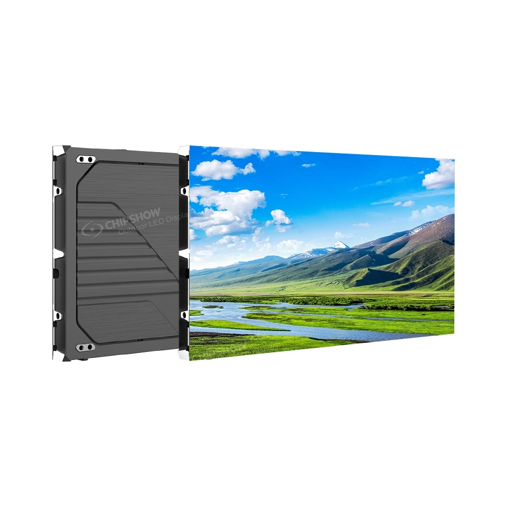
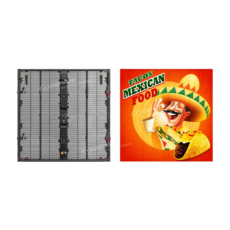
The checks above become concrete on a 320×320 mm module. This format is a common outdoor sign building block, and the same frame, wiring and control questions apply to it in a fixed way. The table maps each check area to the 320×320 mm format and to the C-Fit-Easy platform:
| Check area | What to confirm on a 320×320 mm module | C-Fit-Easy platform |
| Frame | Tolerance budget locked before cutting, since an array builds by multiplication | Die-cast cabinet; product documentation states a cabinet tolerance below 0.1 mm for the described die-cast C-Fit-Easy cabinet |
| Module range | Confirm module mechanics, power and thermal compatibility before any substitution | Cabinet described as compatible with modules from P4 to P20, giving the fabricator a range to design against |
| Wiring | Confirm the module’s Ingress Protection (IP) rating under IEC 60529 | Module protection rating sets the sealing expectation |
| Control | Confirm the receiving card model and routing topology against the actual module count, and store the mapping file with project records | Receiving card chosen against the module’s data interface and the card’s loading limit |
Two cautions on the table above. First, a stated tolerance is only useful when its measurement basis is known, so confirm the definition and inspection method before treating it as an engineering input. Second, the module’s IP rating is specified under IEC 60529 and defines its dust and water resistance; confirm the actual rating and entry sealing against the site exposure rather than assuming a value.
For a monument sign, an electronic message center (EMC) or a roadside pylon, the 320×320 mm module reduces the frame, wiring and control questions to a repeatable set.
Conclusion
Frame, wiring and control read as three separate tasks, but they are one plan. Lock the module drawing and the electrical basis first, carry the tolerance budget across the full array, apply the NEC Article 600 and grounding checks to the finished cabinet, and record the control configuration with the project. Working the checklist in that order catches the expensive mistakes before the metal is cut. Share the sign drawing, the site electrical basis and the control requirements with Chipshow to review the appropriate 320×320 mm module and its integration documentation. Contact us for project-specific configuration and wiring support.
Frequently Asked Questions
Q1:How do I wire a 320×320 outdoor LED module?
Size the power supply against the real module load and headroom, route power away from the data path, seal each cable entry against water, and confirm the module’s IP rating under IEC 60529 matches the site exposure. Apply the NEC Article 600 checks for disconnect, grounding and protection to the completed cabinet.
Q2:Who owns the electrical design, the sign shop or the licensed electrical contractor?
The branch-circuit design, conductor sizing, overcurrent protection and ground-resistance confirmation sit with the licensed electrical designer for the site, because those carry the compliance responsibility. The sign shop supplies the inputs the electrical design depends on: the module load per cabinet section, the service direction, the disconnect position and the operating schedule.
Q3:Which documents should be ready for the AHJ at inspection?
The single-line diagram, the grounding and bonding path, the certificates for listed components, the control configuration record, and a written note of which documents the AHJ has asked to review. Having the frame drawing, single-line diagram and signal-flow diagram dated to the same cabinet revision keeps the submission consistent.
Q4:What should be recorded when a module is replaced in the field?
Record the replacement module’s drawing and revision, the date, the person doing the work, and confirmation that the module matches the array’s mechanical, power and thermal requirements. A replacement note tied to the cabinet revision keeps the as-built record accurate for the next inspection.
Q5:Can a front-service module replace a rear-service module in the same cabinet?
Front service and rear service are different cabinet designs. They change the cabinet depth, the internal rails and the wall standoff, so a rear-service module mounted in a cabinet built for front service becomes a replacement problem. The service direction is decided before the enclosure design, before any replacement is needed.
Not sure which format or pixel pitch fits your project? Try the Chipshow USA LED sign selector to shortlist options.