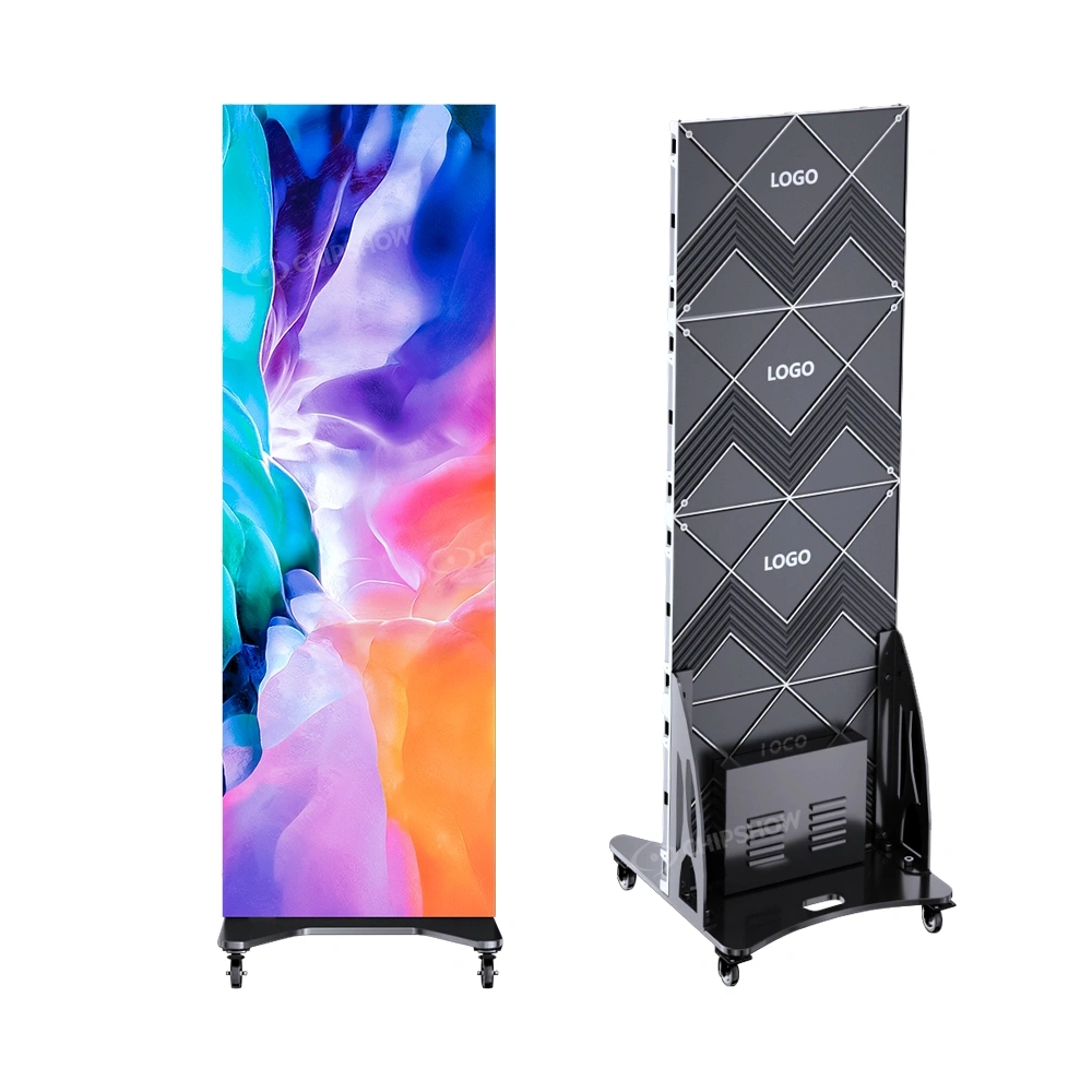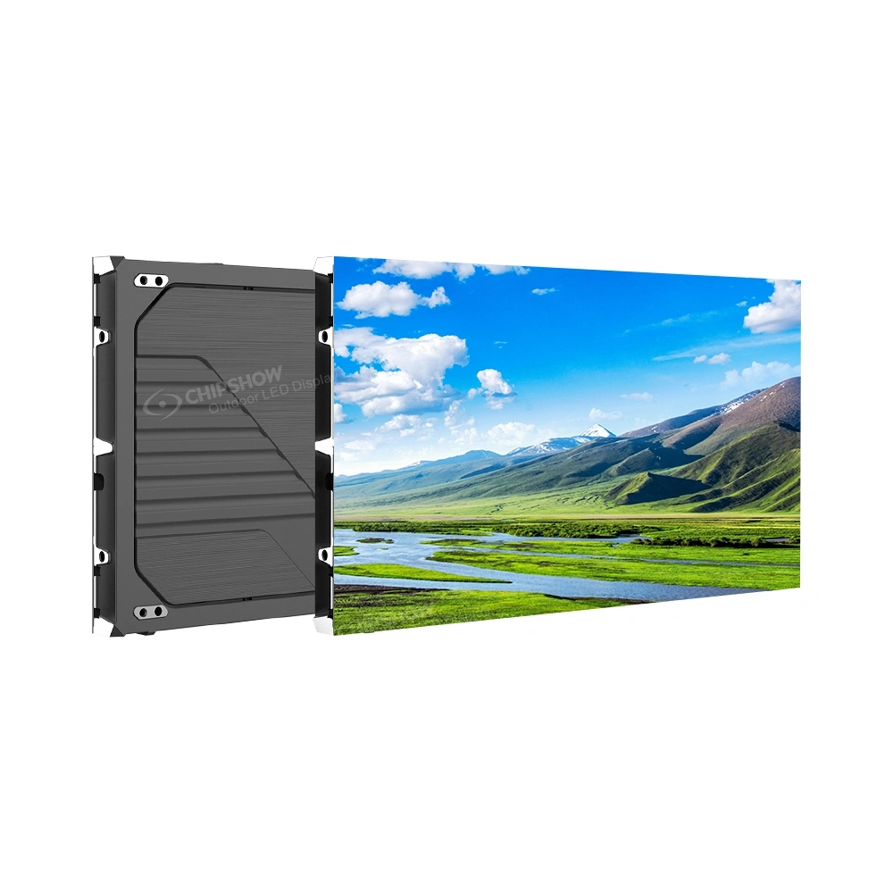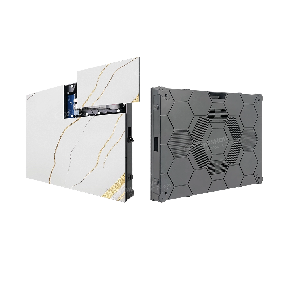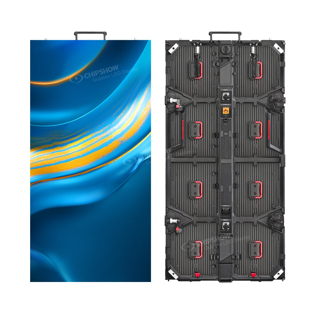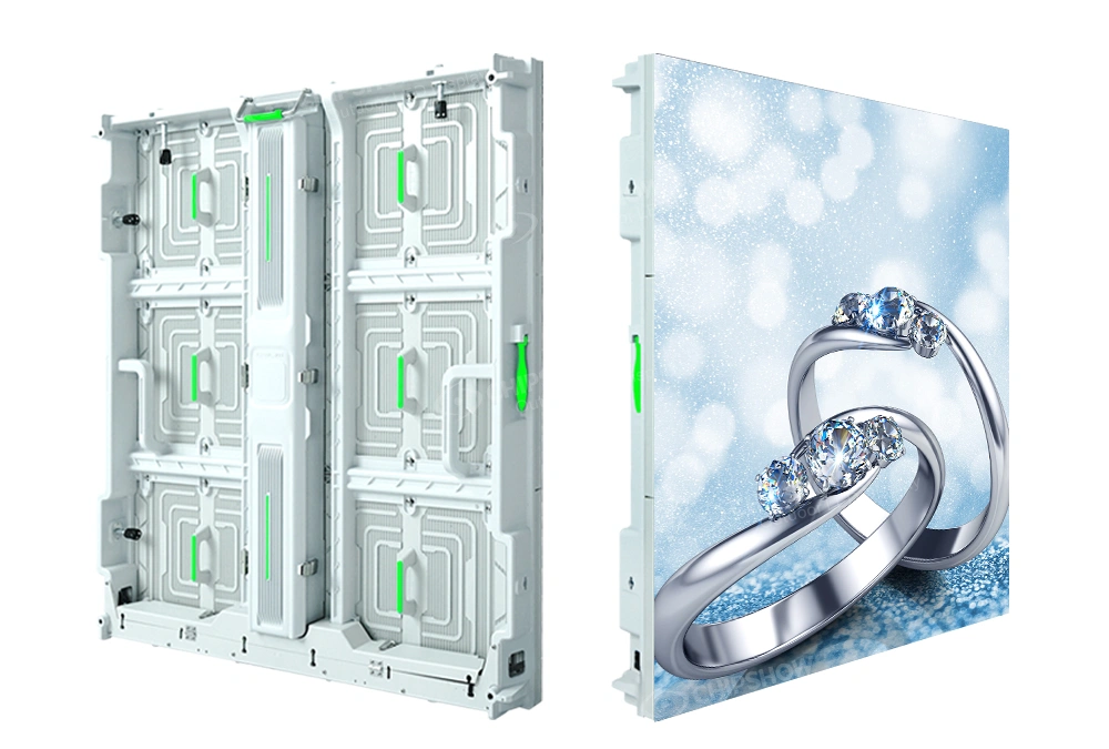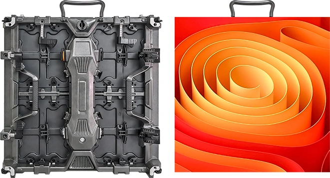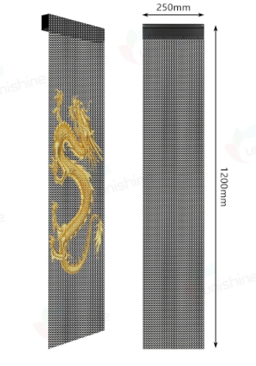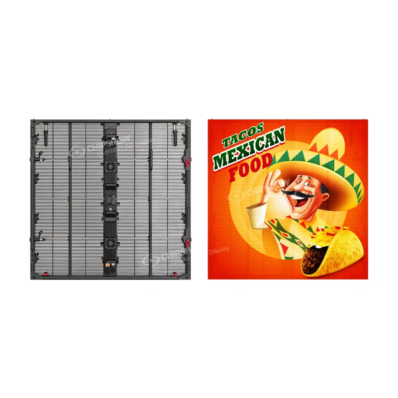
For outdoor LED sign modules, exclude a rear-service arrangement if the installed structure blocks its required entry. Assess front access for all serviceable components: front-service modules alone do not establish front access to power supplies or receiving cards. Where both sides support the required work safely, compare setup steps, equipment positioning and the extent of disassembly. Record the selected component routes and removal clearances before fabrication, using the documented configuration and site conditions to confirm feasibility.
Introduction
Choosing between front and rear service for outdoor LED sign modules requires a site survey and a component-access review. Where a cabinet is mounted against a wall, rear access may be restricted, making front access a candidate to assess. A freestanding monument may offer rear working space, but the survey must also establish whether components can be removed and service equipment positioned safely.
Record access separately for modules, power supplies and receiving cards. Changing a single-service enclosure to provide another access route may require structural or sealing changes. A dual-service system may already provide that route, subject to its documented configuration and the installed surroundings.
This guide stays at the enclosure level. It covers what to survey on site, what to check inside the cabinet, how monument, pylon and storefront structures affect access, and what to include in labor and spare-part planning. The companion piece on outdoor LED sign module checklist covers frame preparation, wiring and control layout.
Front vs Rear Service: The Decision
Front service describes access from the display face; rear service describes access from behind the enclosure. A front-service module designation identifies the module access route. Power supplies and receiving cards may use separate compartments or access routes, which must be checked for the selected system.
Use the conditions below to rule out an obstructed route or identify which option to assess first. For either direction, verify component access, cabinet dimensions and the seals or retention parts disturbed during service.
| Site or configuration condition | Effect on the service decision |
| The completed wall or mounting structure blocks the rear entry required for maintenance. | Exclude the rear-service arrangement that depends on that entry. Assess front access for every component requiring service, including face-side working space. |
| A rear door opens, but a required component cannot pass through the available removal route. | Revise the opening, component layout or service arrangement before selecting rear service. Door movement alone leaves the removal problem unresolved. |
| Modules are front-serviceable, while power supplies or receiving cards require rear access. | Retain rear access for those components, or select a documented configuration that makes them accessible from the front before planning a wall-backed installation. |
| Face-side work would occupy an active passage, while a rear service area is available. | Assess rear service first, subject to component reach, extraction space, equipment access and safe working conditions. |
| Both sides allow the required component work. | Compare setup steps, equipment positioning, work-area controls and the extent of disassembly. Base the choice on those procedures rather than an assumed labor advantage for either direction. |
Record the site measurements and obstructions behind this decision using the survey checklist in the next section.
Standards context. In the United States, NEC Article 600 addresses electric signs and outline lighting, while UL 48 addresses electric signs. These references identify relevant standards, rather than establishing a universal front or rear clearance. Confirm the adopted requirements and project approval process locally. Canadian projects require the applicable Canadian and provincial requirements.
Site Conditions That Decide Access
A site survey for service access is not the same as a site survey for mounting. It records the space a technician needs in order to work, and it is best completed before the cabinet is detailed.
What to record on site:
- Clearance behind the enclosure. The distance from the back of the cabinet to the nearest obstruction, including fences, curbs and utility boxes.
- Ground surface. Paved, gravel, grass or a planted bed, since a soft surface changes what equipment can be set up.
- Door swing radius. For rear service, the arc a door sweeps, and whether that arc crosses a walkway, a parking space or adjacent property.
- Overhead and lateral obstructions. Streetlights, signage arms, tree canopy, and any equipment that would block a lift or scaffold.
- Public exposure. Whether servicing would place a technician inside an active pedestrian or vehicle path.
Project confirmation. Sign type identifies conditions to inspect, rather than prescribing a maintenance direction. The project design team should document the feasible routes and confirm relevant local requirements with the authority having jurisdiction.
Service Access Requirements for Cabinet Drawings
Translate the selected service route into drawing requirements. Use the same checks for front, rear or mixed access; the drawing must show how the proposed configuration fits and how components leave the cabinet.
| Design item | What the drawing must confirm |
| Cabinet depth | Dimension the component layout, cable routing and service space in section view, including hardware or connectors that project into the removal route. |
| Internal mounting | Locate brackets and retention hardware, and show the tool approach needed to release them through the selected opening. |
| Component removal path | Show the sequence from cable disconnection and hardware release to extraction through the opening, including any turning or staged movement required by the service procedure. |
| Sealing interfaces | Mark the joints opened during service and identify the seals to inspect or refit when components, doors or panels are reinstalled. |
| Drainage and venting | Locate drains and vents relative to the cabinet layout and weather exposure. Check that mounting members and surrounding construction leave the intended paths clear. |
| Mounting offset | Dimension the space between the cabinet and supporting structure against installation, thermal and service-access requirements, including routes needed for power and control components. |
Review these details against the manufacturer’s procedure for the selected configuration before issuing fabrication drawings.
Sealing and IP ratings. IEC 60529 classifies degrees of protection provided by enclosures. An IP claim must identify the tested enclosure and configuration. A module enclosure can have a documented rating, but that rating does not automatically establish the protection of the integrated sign cabinet.
Identify the seals disturbed when modules, doors or panels are opened. Follow the documented inspection and refitting procedure for those interfaces. Face openings, rear openings, cable entries and other cabinet joints require assessment as part of the assembled design; maintenance direction alone does not locate every weather barrier.
Matching Access to Sign Type
Monument, pylon and storefront structures create different access constraints. Assess the installed structure and service procedure together.
Monument signs
For a monument near ground level, compare the usable space on both sides with the required component removal and handling routes. Landscaping, curbs and building walls may restrict rear access. Public circulation may restrict work at the face. Include the base and finished surroundings in the access drawing. Appearance and visible joints depend on the enclosure construction, separately from the maintenance direction.
Pylon signs
For an elevated pylon, establish where access equipment can be positioned and which cabinet openings can be reached from it. Check how a removed module or power supply will be handled at working height. Assess traffic controls and property access before selecting the service route.
Storefront and entrance signs
For a storefront cabinet, verify whether the building or recess restricts rear access. Where front service is proposed, check that the face opening allows the required component work and that the service area can be managed safely. Coordinate cabinet depth with the architecture, component layout and applicable mounting requirements.
Planning note. Record the selected routes and their constraints before issuing fabrication drawings.
Labor and Spare Part Planning
Maintenance planning should describe the work procedure, equipment and replacement parts for the installed configuration.
Work setup. Either service direction may require a lift, scaffold or controlled work area, depending on installation height and site access. Ground-level access may simplify equipment setup where the work can be performed safely from that position. Record property access arrangements and any applicable permits or traffic-management requirements.
Personnel qualifications. Identify who is authorized and qualified to perform each task, including electrical work, isolation and work at height. Confirm licensing and permit requirements for the specific activity and jurisdiction. Maintenance direction does not determine the required trade or license.
Spare-part planning. Build the list from the installed parts and documented service procedure. Include compatible modules, power supplies and receiving cards, plus any seals, fasteners or retention parts required during replacement. Where the cabinet has service doors, identify the relevant hinges, latches and gaskets. Front and rear access labels alone are insufficient to define the spare list.
Replacement components. UL 879 addresses electric sign components within its scope. Check the manufacturer’s replacement instructions and the sign’s applicable certification documentation before substituting a component. Confirm project approval implications with the relevant certification body or local authority as appropriate; a component standard alone does not establish compatibility.
Specifying Service Access Before Fabrication
Write the service requirements into the fabrication drawings and request for quotation. Use the following fields to compare the proposed configuration with the surveyed site.
Specification checklist:
- Service direction. Front, rear, or both, stated explicitly for the module section and for the power and control section.
- Clearance dimension. The required working area, door or panel opening, component extraction path and tool clearance on each service side, recorded on the drawing.
- Access method. Hinged door, removable panel, or face-removal module path, with hardware noted.
- Sealing specification. The target ingress protection for the assembled enclosure, the documented scope of any component rating and the joints disturbed during service.
- Module removal path. The sequence for removing and refitting a module, including the tool required and the space needed in front of or behind the display.
- Spare parts list. Modules, power supplies, receiving cards, and the gaskets or hardware used in the documented service procedure.
- Compliance references. The standards and local amendments that apply to the finished sign, confirmed with the authority having jurisdiction before construction.
- Structural interface. How the cabinet attaches to the monument, pylon or wall structure, and whether the service side stays clear after mounting.
Product fit. Module dimensions are one input to service-access planning. Check the removal path, retention hardware and tool clearance for the selected configuration against the enclosure drawings.
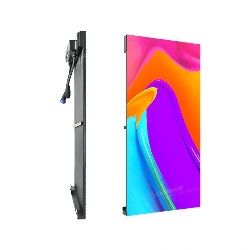
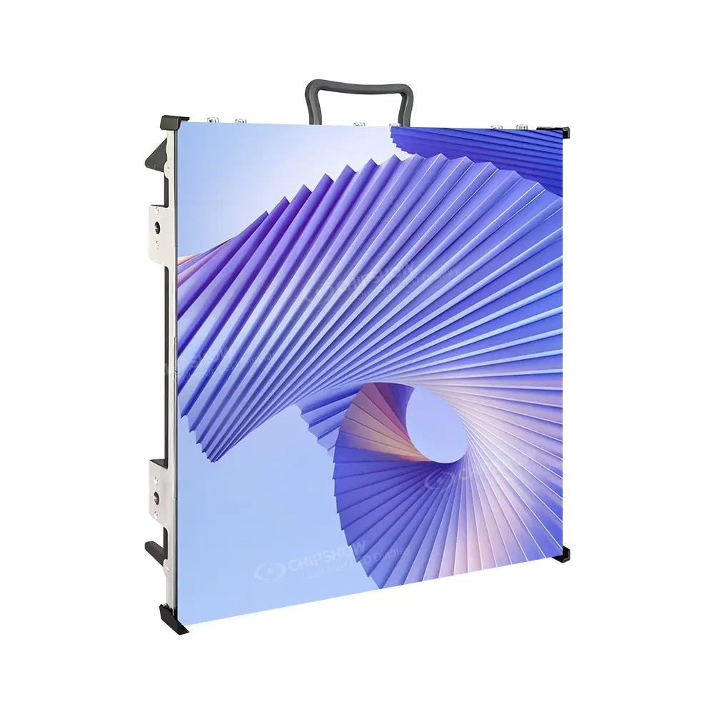
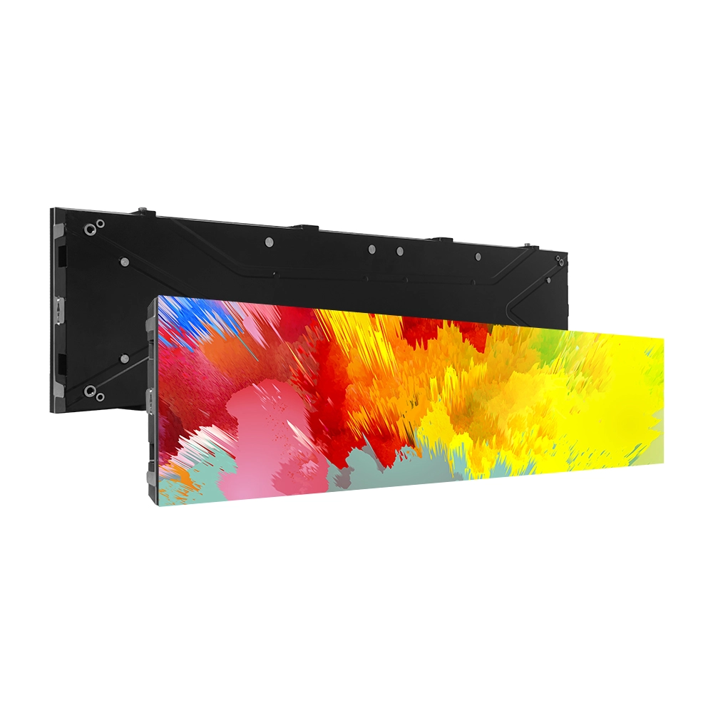
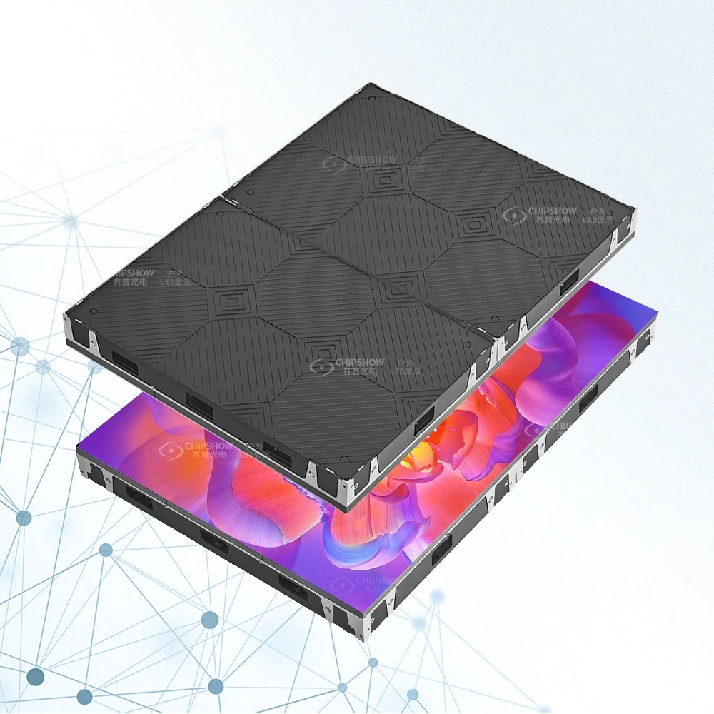
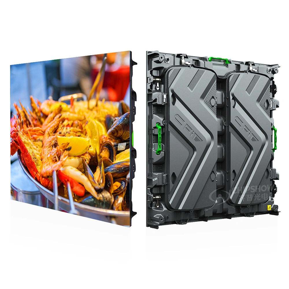
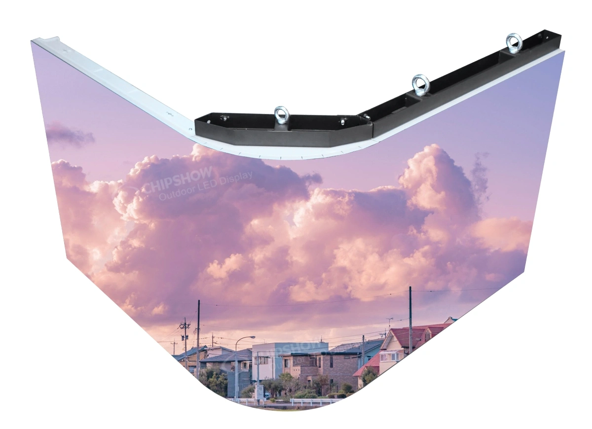
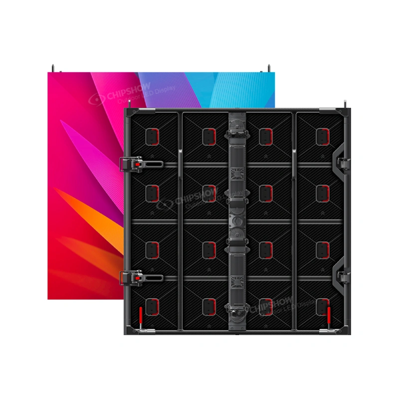
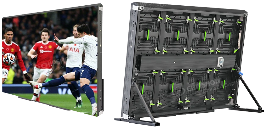
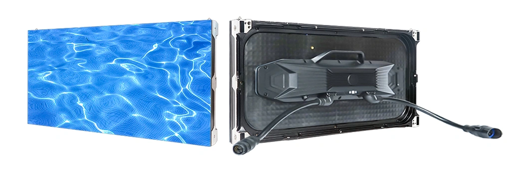
C-Smart modules measure 640 × 320 mm, while C-Fit Easy modules measure 320 × 320 mm. For either platform, confirm the available service direction and the access routes to the modules, power supplies and receiving cards for the selected configuration. The outdoor LED display modules page provides configuration information for this review. Confirm stock availability and shipping location with Chipshow for the selected configuration.
For projects that need the service direction settled against a specific structure, the digital monument LED sign solution page covers enclosure integration for monument formats.
Conclusion
Choose the maintenance direction by checking site access, component routes and the complete enclosure design together. Record clearance, removal procedures, seals and replacement parts before fabrication. For outdoor LED sign module options, Contact us to discuss the selected configuration and its service-access requirements with Chipshow.
Frequently Asked Questions
Q1:How do I decide between front service and rear service before fabrication?
Survey the available working area on both sides, then check the selected configuration for component reach, removal paths, tool clearance and access equipment positioning. Record routes separately for modules, power supplies and receiving cards. Review safe working conditions and applicable local requirements before issuing fabrication drawings.
Q2:What clearance does a rear-service sign cabinet need behind it?
Clearance must accommodate the actual door or panel opening, component extraction, tools, technician movement and any required service equipment. Include cable disconnection and component handling in the review. Determine dimensions from the selected cabinet procedure and applicable project requirements, rather than door swing alone.
Q3:Can the service direction change after installation?
First distinguish an existing dual-service system from a single-service cabinet conversion. A documented dual-service configuration may already support the alternate route if the installed site leaves it accessible. Changing a single-service cabinet may require revisions to openings, mounting hardware, wiring or seals. Confirm the available access routes with the manufacturer. If a conversion is proposed, also verify module compatibility and the revised service procedure.
Q4:Does front service work on a sealed outdoor cabinet?
Front service can be compatible with outdoor weather protection when the enclosure and its service openings are designed and documented for that use. Identify the seals disturbed by maintenance and follow the specified refitting procedure. An IP rating refers to the tested enclosure and configuration; a module rating alone does not establish the rating of the integrated cabinet.
Q5:Which spare parts change with the service direction?
Use the installed configuration and service procedure to determine the list. Include compatible modules, power supplies and receiving cards, plus required seals and retention hardware. Cabinets with service doors may also require hinges, latches or door gaskets. Confirm part references and replacement instructions at handover rather than assigning spares solely by maintenance direction.