TL;DR. A monument sign survey should settle three things: which dimensions change the display layout, which electrical and service conditions a contractor must confirm, and what is still open. Record the available sign area, viewing distance, mounting interface, service-side clearance, power source distance and control location. Circuit capacity, grounding and permit compliance are not survey conclusions. They belong to the licensed electrician, the professional engineer and the authority having jurisdiction.
A survey supplies what the quote needs: dimensions measured on site, and every site condition written down. Both take less time to get right during the visit than to fix later. Responsibility also divides at the survey. The sign company owns the structure and the customer relationship; the electrical contractor owns the circuit; the engineer owns the foundation design; the display supplier owns the module layout and control. The survey records who confirmed which condition, so the proposal can assign each item to a party by name.
This checklist is for sign contractors, sign builders and electrical contractors working on monument and pylon projects with an electronic message center (EMC). It covers what to measure, what to write down about power and access, and which items must leave the site as open questions rather than assumptions.
What a monument sign survey has to produce
A survey produces three outputs: quote inputs, design inputs, and hold points. Quote inputs are the dimensions, quantities and site conditions the estimator prices. Design inputs change the display layout, the enclosure or the service method. Hold points cannot be resolved on site, so they go into the record as assumptions before a price is issued.
The test is simple: can someone who has never visited the site price the work without calling back? A photo set plus an overall width and height passes that test only when the conditions are recorded with them. The price covers a structure, a power run and a service method, and each one has to fit the site.
The survey also separates scope. A monument sign involves a foundation, a structure, an electrical circuit, a display and a content system, and a different party usually designs and installs each one. The digital monument sign guide covers the same components. Recording who confirmed a condition matters as much as recording the condition itself.
Which measurements change the display specification
Eight site measurements change the display layout or the enclosure, not just the price. The table below lists them, the decision each one drives, and how to record it.
| Measurement | What it decides | How to record it |
| Available sign area and aspect ratio | Module count, cabinet split, letter height | W × H in inches and mm, on a scaled sketch |
| Viewing distance and approach direction | Pixel pitch range, brightness setting | Nearest and farthest viewing point; traffic direction |
| Face orientation and ambient light | Brightness requirement, shading or hood need | Compass direction per face; what shades it |
| Mounting interface and depth | Enclosure depth, bracket design, whether the display sits in a cabinet or on a frame | Opening depth, substrate type, photo with scale |
| Service side and clearance | Front-access or rear-access configuration | Clear distance per service side, measured from the face; obstructions noted |
| Power source distance and route | Conduit length, whether a new trench is needed, voltage-drop review by the electrician | Straight-line distance and route; obstacles noted |
| Control equipment location | Cabinet or rack position, data route | Control equipment position; distance to display |
| Base or existing structure condition | Whether the structure can be reused | Photo only; no structural conclusion on site |
Available sign area changes the display most often. A wide, shallow face constrains the module split more than its total area suggests, because the display divides into whole modules and the remainder becomes frame or blanking. Service clearance comes next. Where the rear of the sign faces a wall, a hedge or a property line, the display has to be serviced from the front; an open rear may allow a rear-access enclosure. Viewing distance sets a pitch range, not a single pitch, so the viewing point used every day matters more than the farthest one.
The electrical record: what to note and what to leave to a licensed electrician
The survey records electrical conditions. The electrician sizes the circuit, the conductors and the breaker from that record. The record lists the location of the service panel and how much space is left in it, whether a disconnect exists and where, the practical conduit route and its length, whether a grounding electrode is visible, and whether a separate data pathway exists.
Existing signage on the same property is a useful reference, because a listed sign carries its rating. NEC 600.4 requires the manufacturer’s identifier and the electrical ratings in volts and amps. 600.4(E) adds a marking that points installers to the installation instructions on signs shipped in sections. 600.23(F) marks a power supply that includes secondary-circuit ground-fault protection. The nameplate of an existing sign gives a real load figure from a comparable installation instead of an estimate.
The record also has a limit. The left column takes what can be seen: location, count, presence, distance. The right column stays blank until the electrician, the engineer or the authority having jurisdiction fills it in, because those items have to be calculated or signed off.
| Record on site | Leave to the licensed electrician, engineer or AHJ |
| Panel location and the number of visible spare spaces | Available capacity, breaker sizing and conductor sizing |
| Existence and location of a disconnect | Whether the disconnect location satisfies the applicable code and the AHJ |
| Conduit route, length and obstacles | Voltage-drop calculation and conduit fill |
| Whether a grounding electrode is visible | Grounding electrode condition, bonding method and adequacy |
| Existing sign nameplate rating in volts and amps | Whether the existing circuit can be reused |
| Control equipment position | Whether the proposed supply arrangement is acceptable for the installation |
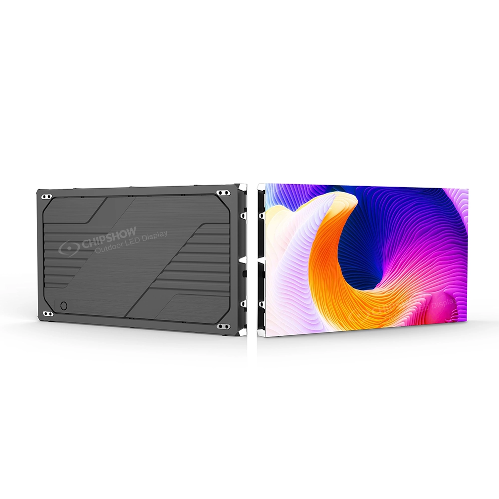
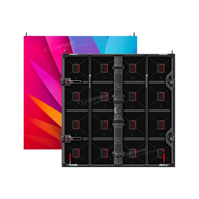
Power per area sets the load the electrician has to supply, and the rated load per power supply sets how many modules each one can carry. Both come from the display supplier’s datasheet, and neither is measured on site. To show what those figures look like, the example below uses Chipshow’s published specifications. The C-Smart modular LED sign is specified at 700 W/㎡ maximum and 300 W/㎡ average for P4, and one power supply carries 18 modules at 110 V or 36 at 220 V (A). Those figures give the electrician a load to work from; they do not size a circuit. Supply voltage, rated current per cabinet and conductor size still come from the product nameplate and the electrician’s calculation.
Where US sign code and permitting enters the survey
Permitting and electrical approval are two separate processes, and the survey supplies inputs to both. The permit process covers zoning, setbacks, height limits, sign area allowances, landlord criteria and the submittal package the local authority requires. The electrical process covers how the sign is listed and marked once installed, the circuit, the disconnect and the grounding.
The listing question is decided before fabrication, not on site. UL 48 covers electric signs, art forms and outline lighting used in accordance with NFPA 70, and its scope includes changing-message signs, including LED types (B). UL 879 covers sign components, and UL 879A covers LED sign and retrofit kits (B). NEC 600.3 requires signs to be listed and installed in conformance with that listing (B). Which edition applies is decided locally. For a large or non-standard monument outside a manufacturer’s standard coverage, a UL field evaluation produces a label and a report that the AHJ can accept for that specific project (B).
A custom monument assembled from modules, a frame, a power supply and a control system is generally treated as a sign for the purpose of the listing requirement. The assembly, not only the module, has to satisfy the listing requirement. The survey should therefore record whether the project is a new sign, a replacement or a retrofit, because the three paths need different submittals.
Utility location belongs before fabrication as well. State dig laws require notice to the 811 one-call center before excavation begins, and the notice period varies by state. The survey records whether a locate has been requested and whether any marked utilities fall inside the proposed footprint. The outdoor LED screen installation guide documents the permitting, foundation, electrical and rigging work that comes after the survey.
Structural and environmental loads are recorded, not calculated. Wind exposure, snow load and soil conditions determine the foundation design under the applicable building code and ASCE 7 load provisions. A professional engineer signs that design where the jurisdiction requires it. The survey contributes the evidence: site exposure, nearby obstructions, visible soil and drainage, and the depth of any existing foundation being reused.
Installation and service access
Access conditions decide the installation method more often than the sign size does. The survey should record the staging area, the reach available from the nearest practical parking position, and overhead clearance along the approach. It should also record any fire lane or loading restriction that limits where a vehicle can stand, the swing of any service door, and the space needed to remove a module or a power supply.
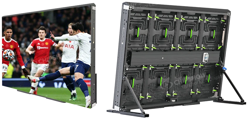
Service access deserves its own measurement. A front-service module needs clearance in front of the face; a rear-service module needs standing space behind the sign and enough depth to come out. On a sign set at a property line, rear space often decides which configuration is possible. The monument and pylon comparison shows how each structure type changes that access. The record should also note where spare modules and power supplies can be stored, whether the top of the face needs a ladder or a lift, and whether the frame can drain.
The display needs open space above and below it inside the enclosure. The example below comes from Chipshow’s published specifications. C-Smart requires at least 5 cm for air convection, and no crossbeam or support may cover the vents (A). A face sized to the display outline alone fills that gap, so the 5 cm belongs in the survey record and in the drawing review, not in a note after fabrication.
Responsibility matrix
The matrix below records who normally confirms each item; the actual split must be written into the proposal. Putting that split in the proposal turns a verbal understanding into a line by line assignment, and a line by line assignment is hard to argue with later.
| Item | Normally confirmed by | What the display supplier provides |
| Sign structure, foundation and geotechnical conditions | Professional engineer, or the sign company’s engineer of record; geotechnical engineer where required | Module dimensions, weight per area and mounting points; nothing for soil or foundation |
| Electrical circuit, disconnect and grounding | Licensed electrical contractor, inspected by the AHJ | Power specification and connection requirements |
| Permit application and zoning compliance | Sign company or permit expediter, approved by the AHJ | Drawings and product data as requested |
| Listing and field evaluation of the sign | Sign manufacturer or assembler, with UL or an approved field evaluation body | Listed components and product documentation |
| Display and control system | Display supplier, agreed with the sign company | Pitch range, module dimensions, power per area, power supply load per voltage, control options and data requirements |
| Installation and commissioning | Installing contractor, witnessed as required | Installation instructions and commissioning support |
| Service access and spares | Sign company with the owner | Front or rear service configuration |
Chipshow’s role in this matrix is the display and control scope: module dimensions, the pitch range available, the power per area and the service configuration. The structure, the foundation, the circuit and the permit remain with the parties listed in the second column. Writing that split into the proposal keeps a late change on the electrical side from being read as a display defect.
Turning the survey into a quote-ready handoff
A handoff is complete when every item is marked confirmed, assumed or hold. Confirmed items carry a measurement or a document. Assumed items carry the assumption and the reason it could not be verified on site. Hold points carry the condition that has to be met before fabrication starts.
Five conditions turn the price into a hold point: the proposed location conflicts with a marked utility or a setback; the electrician has not verified the power source distance or capacity; the survey has not inspected the mounting interface; the measured clearance cannot take the module or power supply removal the selected configuration needs; the listing route for a custom assembly is unresolved. The design work can continue in all five cases. Each one stops a firm price, because the cost of the alternative may exceed the margin on the project. The cost factors in the monument sign buying guide show which budget lines those conditions move.
The photo set should be organized to match the checklist rather than the order of the visit: one wide shot of the site with the proposed location marked, one shot per service side with a scale reference, one of the electrical panel with the door open, one of the proposed conduit route, and one of any condition that could not be measured.
Field checklist
The table repeats the items above in the order of a site visit, with the recording format for each one. It records conditions; the decisions on those conditions stay with the parties named in the matrix.
| # | Item | Record |
| 1 | Project type and existing sign label | New sign, replacement or retrofit; volts and amps from the existing nameplate, photographed |
| 2 | Location and setbacks | Position marked on a scaled site plan, with measured distances to curb, property line and building |
| 3 | Available area and aspect ratio | Width × height in inches and millimeters |
| 4 | Viewing conditions and face orientation | Nearest and farthest viewing points with approach direction; orientation and shading of each face |
| 5 | Mounting interface and base condition | Opening depth, substrate type, visible base condition, all photographed |
| 6 | Service, convection and maintenance access | Clearance at each service face, 5 cm above and below the display for convection, spare storage, lift need |
| 7 | Power source, disconnect and conduit | Panel location and visible spare spaces, disconnect location, conduit route and length |
| 8 | Grounding | Whether a grounding electrode is visible |
| 9 | Control position and data route | Where control equipment can sit, and the data path to the display |
| 10 | Utility locate | Whether a locate has been requested and markings are present |
| 11 | Installation access | Staging area, lift position and overhead clearance |
Conclusion
A survey earns its cost when it settles three things: what the display depends on, what a contractor must confirm on site, and what stays open until the electrician, the engineer or the AHJ answers. Run the checklist once and record who confirmed each item, and the quote has a basis.
For a project with an EMC, the digital monument LED sign solution shows the display options those measurements feed into. Send the completed record and site photos through the contact page for a layout review.
FAQ
Q1:Who should carry out a monument sign site survey?
Someone who can measure the site, read an electrical panel and recognize a structural condition. In practice that is a sign company project manager, a survey crew or the electrical contractor, all working from the same checklist. The survey does not replace the electrician’s or the engineer’s own site visit where the project requires one.
Q2:Does the display supplier design the sign structure or the foundation?
No. The display supplier specifies the module dimensions, the weight per area, the mounting points and the power per area. The structure, the foundation and the anchoring design remain with the sign company, its engineer or the engineer of record, and are confirmed against the applicable building code and ASCE 7 load provisions.
Q3:What should be recorded when the nearest power source is far from the sign?
The straight-line distance, the practical conduit route including crossings and paved surfaces, the panel location and any visible spare capacity, and whether a disconnect already exists near the sign. The electrician uses those inputs to calculate voltage drop and conductor size; the survey should not estimate either.
Q4:Which survey items most often change the display specification?
Available sign area and aspect ratio, viewing distance, service-side clearance and the position of the control equipment. Each of them changes the module layout or the enclosure rather than only the price, and each is cheap to confirm on site and expensive to change after fabrication.